Transformer Based Products
Transformer Based Products
| Line Power Conditioner Voltage Regulator Voltage Converter Frequency Converter AC Line Reactor |
Line Power Conditioner
A line power conditioner is an electronic device, commonly taking the form of a power strip, that smoothes out the peaks and dips of common household AC power.They create smooth power for precision electronics, such as computers and sound equipment hi end televisions and projectors. Many power conditioners also function as Surge Protectors.
Power conditioners are different from the typical uninterruptible power supply in that they continuously charge the battery and continuously run the equipment off battery power. Most UPS’s simply pass the source power straight through while the source power is on. This can cause some sensitive equipment to fault or perhaps even be damaged in extreme cases. A dual conversion online UPS is a kind of power conditioner.
When running an electric generator, using a power conditioner for electronics is a good idea. Audiophiles appreciate that electrical signal noise doesn't come through speakers when a power conditioner is used to condition the electricity powering the speakers.
Ideally, AC power comes in the form of a pure sine wave. Some generators produce power that is closer to a square wave than a sine wave. Conditioning this kind of power requires more than a power strip-sized power conditioner. A larger unit with a battery is generally required for this application.
Under low voltage conditions, computer equipment's internal power supply and circuitry must compensate by working harder. Repeated exposure to brownouts can overheat these sensitive components causing keyboard lock-ups, data corruption and in some cases total system failure.
Other failures in computer efficiency can be symptoms of power spike and surge problems. These can appear as garbled data, systems lockups, general protection faults, and slowed transmission. While many surges and spikes are products of nature, like lightning strikes and many more are products of man - like copier or laser printer cycling.
Line conditioners prevent power surge problems by keeping your equipment working through brownouts without using emergency CVCF & VVVF Power Sources like Uninterrupted Power Supply systems or auxiliary generators. Line conditioners automatically adjust under- and over- voltages to provide safe, computer-grade AC power.
Power conditioners are the best choice when setting up a server environment.
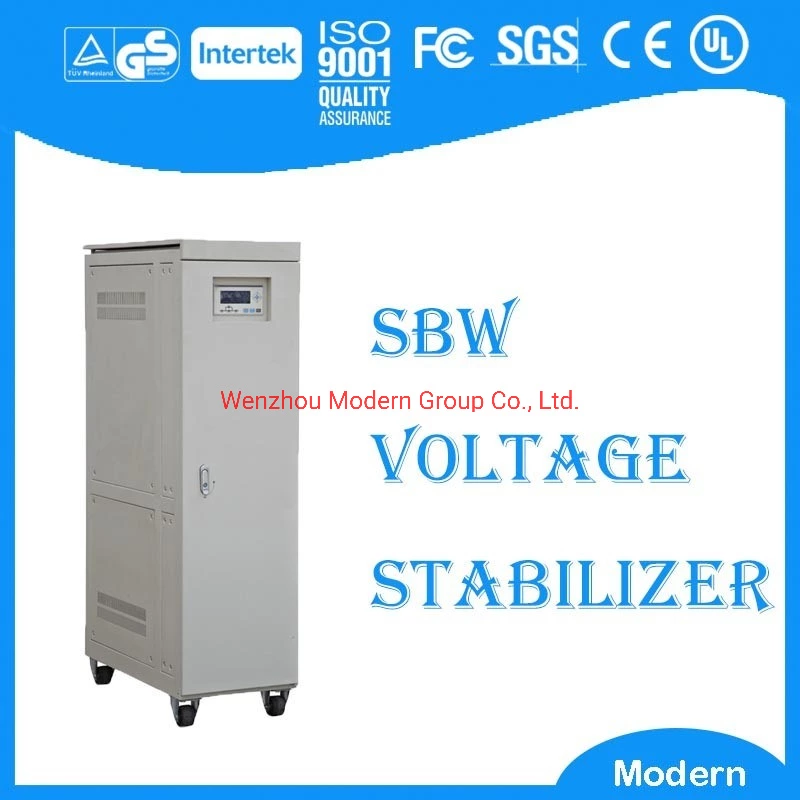
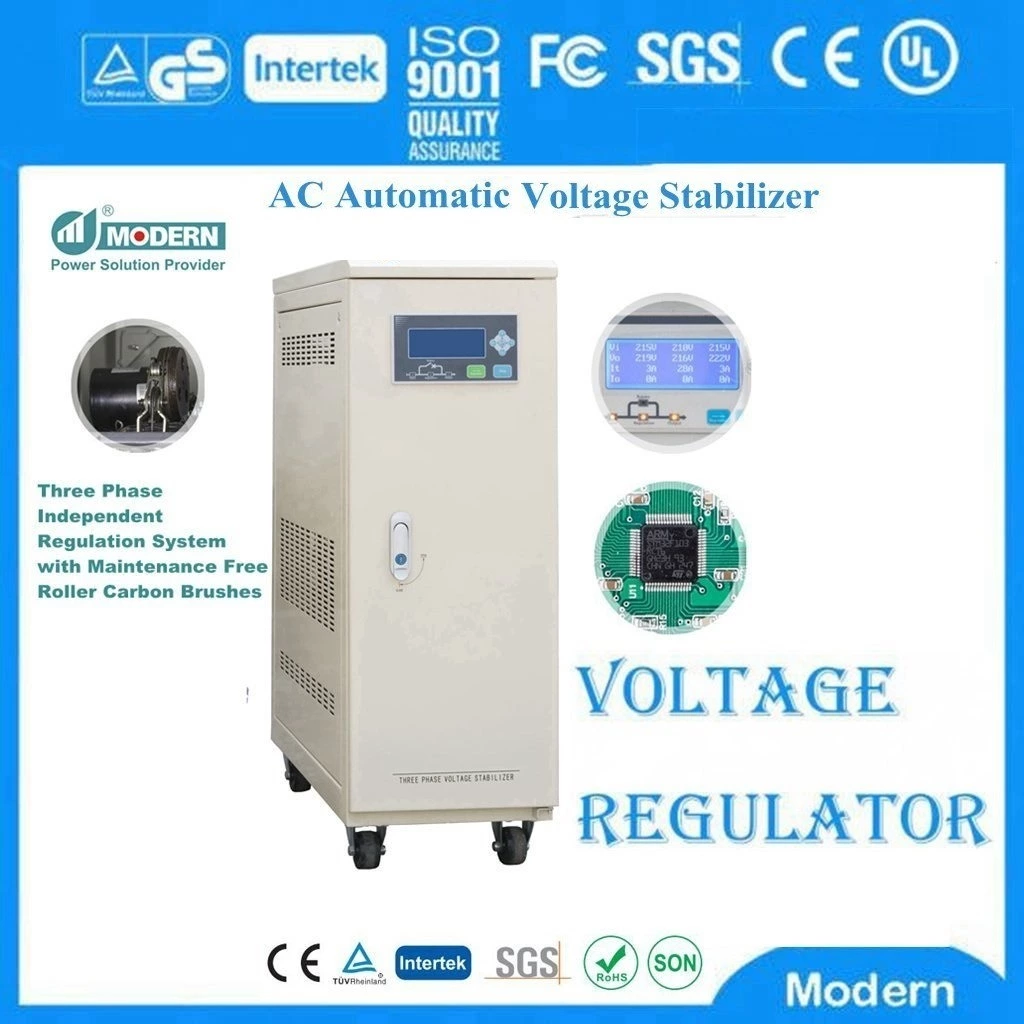
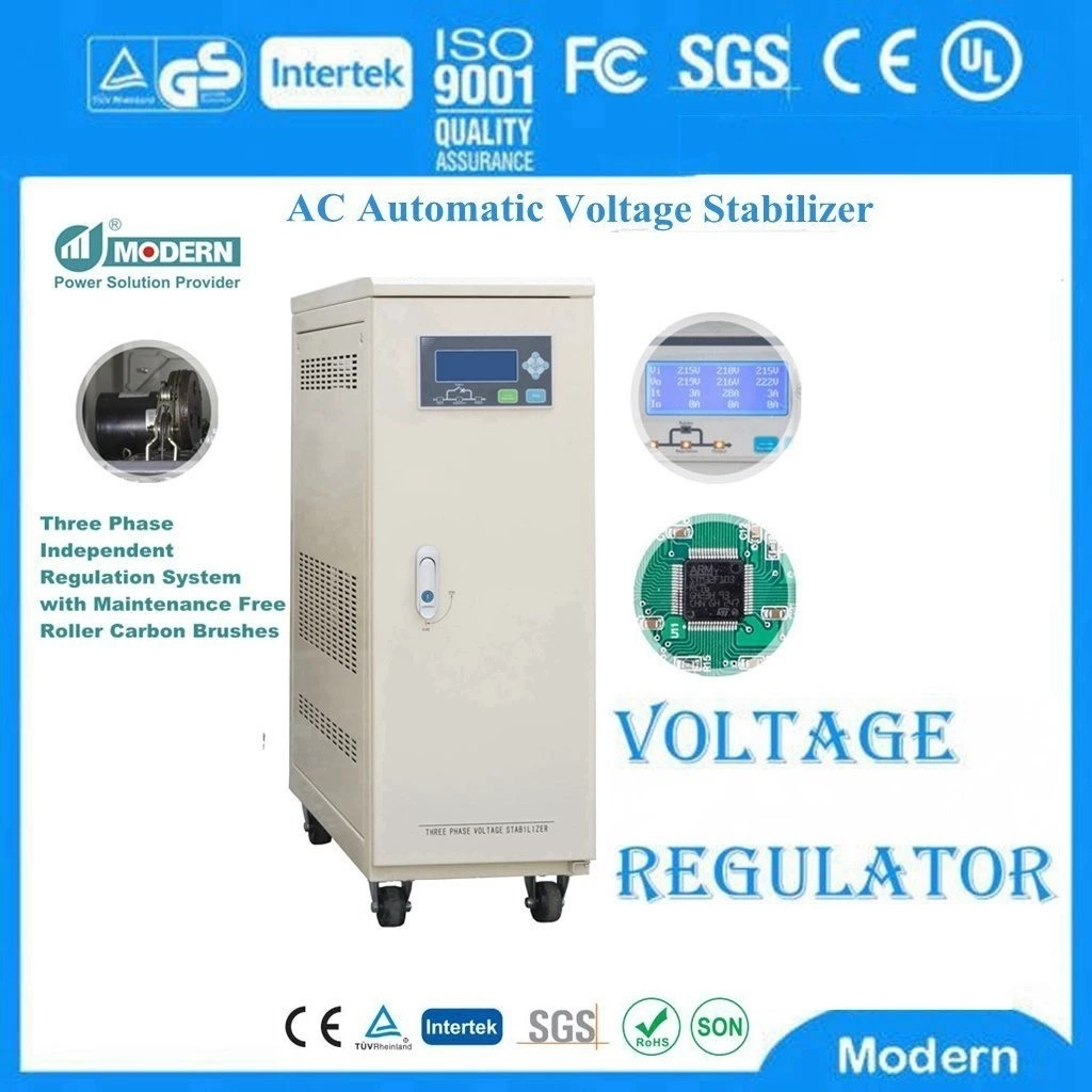
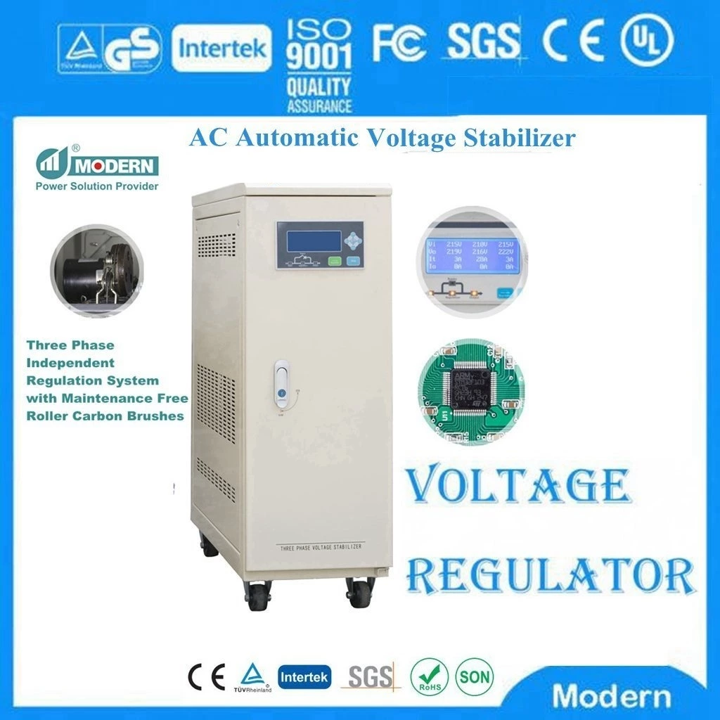
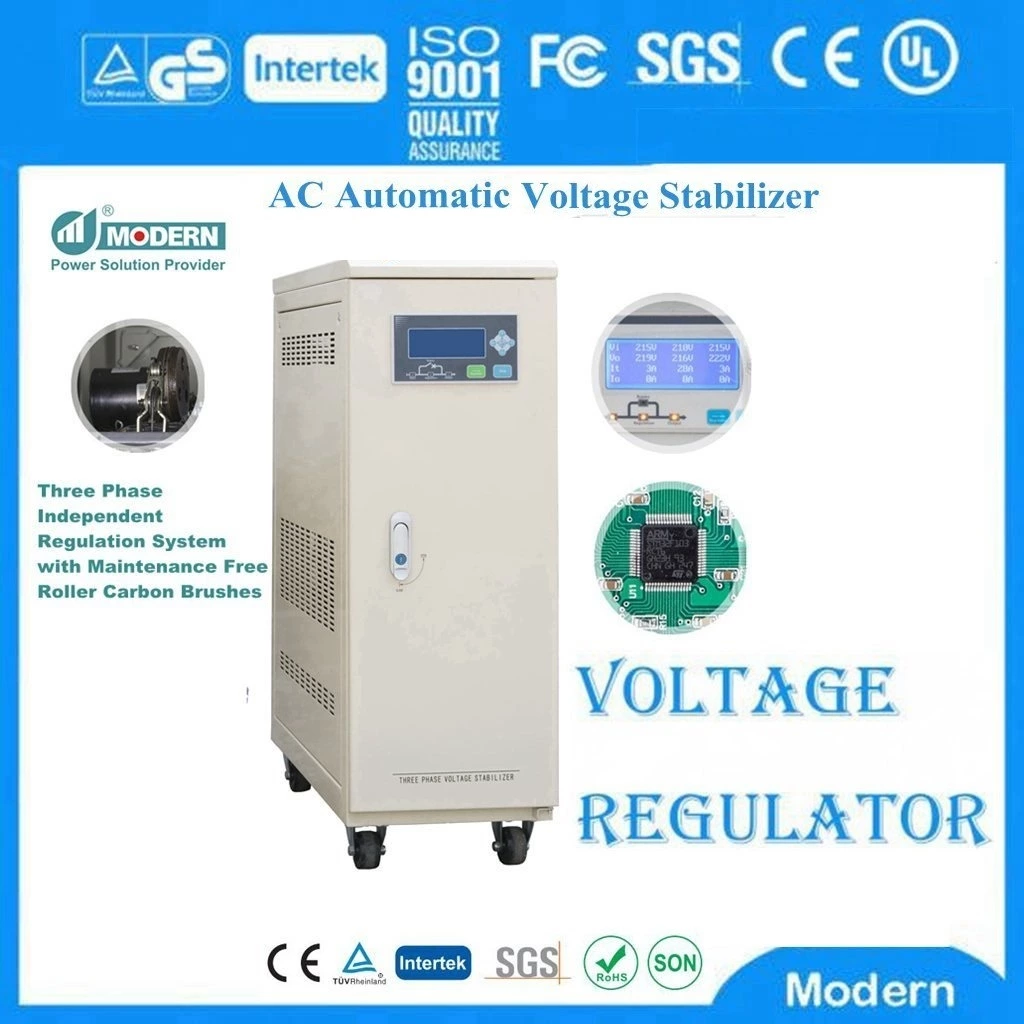
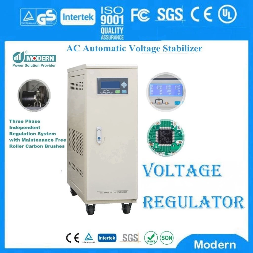
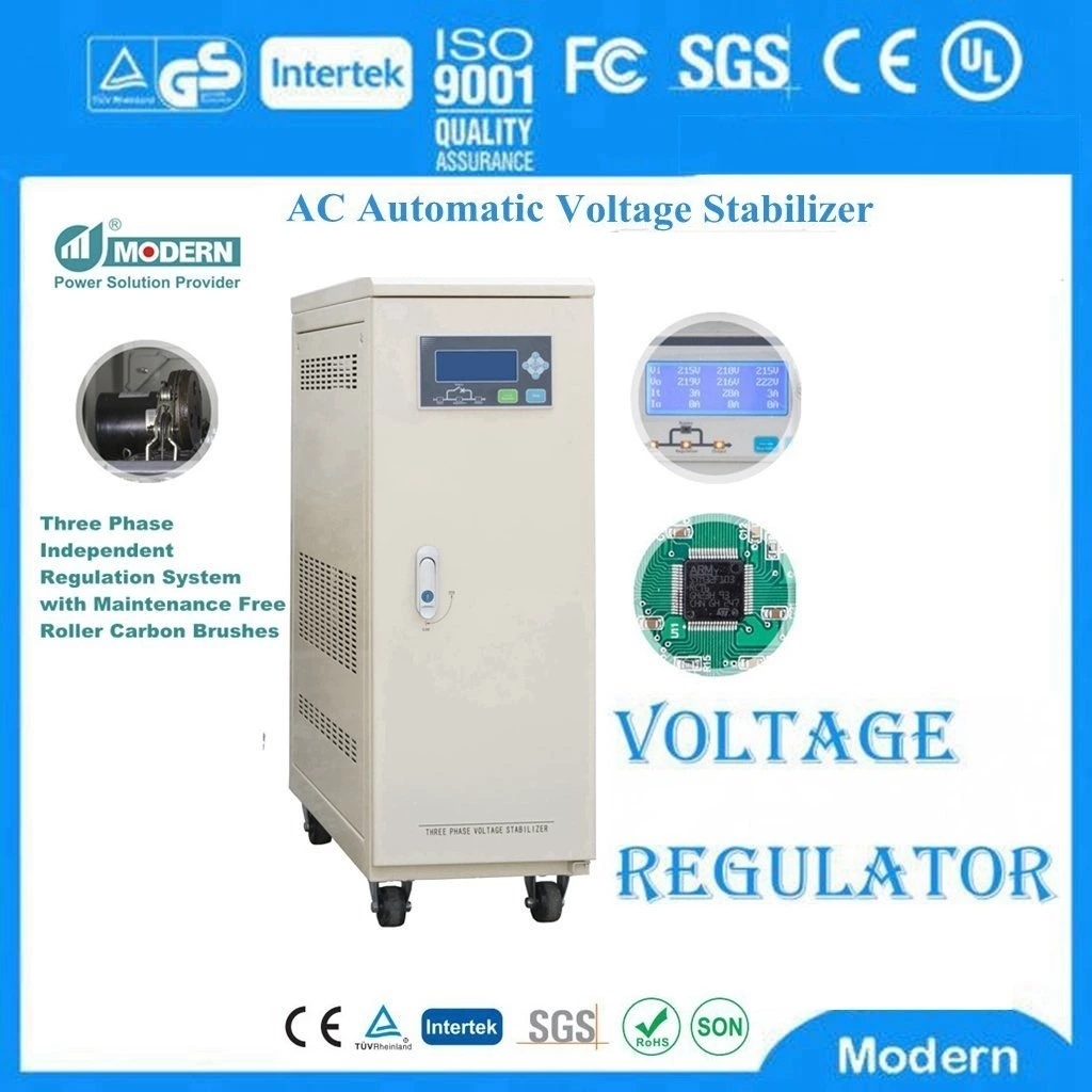
Voltage Regulator
A voltage regulator is an electrical regulator designed to automatically maintain a constant voltage level.
It may use an electromechanical mechanism, or passive or active electronic components. Depending on the design, it may be used to regulate one or more AC or DC voltages.
With the exception of shunt regulators, all voltage regulators operate by comparing the actual output voltage to some internal fixed reference voltage. Any difference is amplified and used to control the regulation element. This forms a negative feedback servo control loop. If the output voltage is too low, the regulation element is commanded to produce a higher voltage. For some regulators if the output voltage is too high, the regulation element is commanded to produce a lower voltage; however, many just stop sourcing current and depend on the current draw of whatever it is driving to pull the voltage back down. In this way, the output voltage is held roughly constant. The control loop must be carefully designed to produce the desired tradeoff between stability and speed of response.
Electromechanical regulators have also been used to regulate the voltage on AC power distribution lines. These regulators generally operate by selecting the appropriate tap on a transformer with multiple taps. If the output voltage is too low, the tap changer switches connections to produce a higher voltage. If the output voltage is too high, the tap changer switches connections to produce a lower voltage. The controls provide a deadband wherein the controller will not act, preventing the controller from constantly hunting (constantly adjusting the voltage) to reach the desired target voltage.
Every electronic circuit is designed to operate off of some supply voltage, which usually assumed to be constant. A voltage regulator provides this constant DC output voltage and contains circuitry that continuously hold the output voltage at the design value regardless of changes in load current or input voltage.
A linear regulator operates by using a voltage-controlled current source to force a fixed voltage to appear at the regulator output terminal. The control circuitry must monitor the output voltage, and adjust the current source to hold the output voltage at the desire value. The design limit of the current source defines the maximum load current the voltage regulator can source and still maintain regulation.
The output voltage is controlled using a feedback loop, which requires some type of compensation to assure loop stability. Most linear regulators have built-in compensation, and are completely stable without external components.
Another characteristic of any linear regulator is that it requires a finite amount of time to correct the output voltage after a change in load current demand. This "time lag" defines the characteristic called transient response, which is a measure of how fast the regulator returns to steady-state conditions after a load change It is import to note that a sudden increase or decrease in load current demand will cause the output voltage to change until the loop can correct and stabilize to the new level.
AC Line Reactor
Let's first define what a reactor is. Essentially a reactor is an inductor. Physically it is a coil of wire that allows a magnetic field to form around the coil when current flows through it. When energized, it is an electric magnet with the strength of the field being proportional to the amperage flowing and the number of turns. A simple loop of wire is an air core inductor. More loops give a higher inductance rating. Quite often some ferrous material such as iron is added as a core to the winding. This has the effect of concentrating the lines of magnetic flux there by making a more effective inductor.
Going back to basic AC Circuit theory, an inductor has the characteristic of storing energy in the magnetic field and is reluctant to a change in current. The main property of a reactor is it inductance and is measured in henrys, millihenrys or microhenrys. In a DC circuit ( such as that of the DC bus in an AC drive), an inductor simply limits the rate of change of current in the circuit since current in an inductor wants to continue to flow at the given rate for any instant of time. That is to say, an instantaneous increase or decrease in applied voltage will result in a slow increase or decrease in current. Conversely, if the rate of current in the inductor changes, a corresponding voltage will be induced.
Like most things there are side-effects to using a reactor. Though these issues should not prevent the use of a reactor, the user should be aware of and ready to accommodate these effects. Since a reactor is made of wire (usually copper) wound in a coil, it will have the associated losses due to wire resistance. Also, if it is an iron core inductor ( as in the case of most reactors used in power electronics) it will have some "eddy current" loss in the changing magnetic field and the iron molecules being magnetically realigned. In general a reactor will add cost and weight, require space, generate heat and reduce efficiency.
Sometime the addition of a line reactor can change the characteristics of the line you are connected to. Other components such as power factor correction capacitors and stray cable capacitance can interact with a line reactor causing a resonance to be set up. Ac drives have exh1ibit a relatively good power factor and do not require the use of correction capacitors. In fact, power factor correction capacitors often do more harm than good where AC drives are present.
With these side effects, why use a reactor? The fact is there are good reasons to install a reactor under certain conditions. Let's start with the input side of a drive.
Use an AC Line Reactor at the Input to reduce Harmonics:
As you may already know, most standard "six pulse" drives are nonlinear loads. They tend to draw current only at the plus and minus peaks of the line. Since the current wave-form is not sinusoidal the current is said to contain " harmonics". For a standard 3 phase input converter (used to convert AC to DC) using six SCR's or six diodes and a filter capacitor bank the three phase input current may contain as much as 85% or more total harmonic distortion. If a line reactor is installed the peaks of the line current are reduced and somewhat broadened out. This makes the current somewhat more sinusoidal, lowering the harmonic level to around 35% when a properly sized reactor is used. This effect is also beneficial to the DC Filter capacitors. Since the" ripple current" is reduced. The capacitors can be smaller, run cooler and last longer.
Using an AC Line Reactor as a line voltage buffer:
In some cases, other switch gear on the line such as contactors and disconnects can cause line transients, particularly when inductive loads such as motors are switched off. In such cases, a voltage spike may occur at the input to the drive that could result in a surge of current at the input. If the voltage is high enough, a failure of the semiconductors in the DC converter may also result. Sometimes a reactor is used to "buffer from the line". While a DC link choke, if present will protect against a current surge, it cannot protect the converter from a voltage spike since a link choke is located after the converter. The semiconductors are exposed to whatever line voltage condition exists. For this reason a reactor at the input to the drive may be of some help.
A reactor does not fix grounding issues nor does it provide isolation. Keep in mind that while a reactor provides some buffering, it does not provide isolation and cannot take the place of an isolation transformer.
AC Line Reactors at the drive output to increase load inductance:
Applying a rector at the output of a drive is sometimes necessary, Again, all of the "side- effects" as previously stated hold true. If the motor has a "low leakage inductance" a reactor can help bring the total load inductance back up to a level that the drive can handle. In some rare cases where a strange motor configuration or a motor with 6 or more poles is used, the motor inductance may be too low and a reactor may be needed. Running multiple motors on one drive may also result in a low inductance load and the requirement of an output reactor.
Reactors at the drive output to reduce the effect of reflected wave:
A reactor at the output of a drive is sometimes installed in order to prevent a reflected wave voltage spike when long motor leads are required. This is not always a good practice. Though the reactor will slope off the voltage rise time providing some benefit, it is not likely to limit the peak voltage at the motor. In some cases, a resonance can be set up between the cable capacitance and reactor that causes even higher voltages to be seen at the motor. In general, a motor terminator is a better solution. If a reactor is installed at the output, it is most likely part of a specially designed "reflected wave reduction" device that also has damping resistors in parallel. If a reactor is used at the output, it should be located as close to the drive end as is possible.
Sizing an AC Line Reactor:
The first rule is make sure you have a high enough amp rating. In terms of the impedance value, you will usually find that 3% to 5% is the norm with most falling closer to 3%. A 3% reactor is enough to provide line buffering and a 5% reactor would be a better choice for harmonic mitigation if no link choke is present. Output reactors, when used, are generally around 3%. This percent rating is relative to the load or drive where the reactor impedance is a percent of the drive impedance at full load. Thus a 3% reactor will drop 3%3# of the applied voltage at full rated current.
A reactor is not a magic wand but can prevent certain problems when applied properly. Reactors can be helpful in providing some line buffering or adding impedance especially for drives with no DC link choke. For small drives they may be needed to prevent inrush or provide reduction in current harmonics when many small drives are located at one installation. At the output they should only be used to correct low motor inductance and not as a motor protection device.
Use a reactor:
To add line impendence.
To provide some light buffering against low magnitude line spikes.
To reducing harmonics.
To compensating for a low inductance motor.
Only as part of a filter for reflected wave reduction
Voltage Converter
A voltage converter changes the voltage of an electrical CVCF & VVVF Power Source and is usually combined with other components to create a power supply. The term "voltage converter" is sometimes used as a generic term for a power supply. A voltage converter or a power supply may be called a "transformer" even if it does not contain an actual transformer as the term is used in electronics.
The most common use of the voltage converter is to change voltage in outlet so we can use appliances in different geographical area. Most single phase alternating current electrical outlets in the world have a voltage range of 210 to 220 volts or a range of 110 to 120 volts. Converters usually can only double the voltage or halve the voltage but some are set up to do both.
Often these are sold with plug end adaptors that provide conversion of the size and shape of the plug end. If voltage conversion is not needed the plug adaptor can be used without a voltage converter.
There are a number of methods for converting voltage. For Alternating current (AC) a transformer can be used to decrease or increase the voltage. The common power supplies for small electronics usually have a transformer that drops the voltage down to relatively small voltage ranging from 4.5 to 12 volts, a full-wave rectifier to convert the AC to a pulsed Direct Current and some additional components to flatten the wave. Some devices have only a transformer in the external power supply with any rectifier or additional power conditioning provided inside the appliance.
Voltage converters and transformers do not convert cycles. They can only be used to convert the voltage. Step down voltage converters will convert from 220V to 110V thus. allowing you to use your US products abroad in 220V countries. Step up transformer will convert voltage from 110V to 220V thus, allowing you to use 220V products in the US. Most voltage transformers are both step up and down, you can switch them to operate as step down or step up.
Selecting the correct Voltage converter
1. Look for the voltage rating on your appliance, if the rating states something similar to 110V-240V that means your product is dual voltage, in this case you can use your product in a 220v without a voltage converters. Most laptops and camcorder battery chargers are dual voltage. However, you may need a plug adapter to plug it in to the outlets abroad. If the voltage rating states 110V or 120V it means that your product is only single volt and it will require a step down converter for use in 220V countries abroad.
2. Now that you know that you require a voltage converter, you need to determine which one or what kind. Look for the watt rating on the appliance or calculate the wattage by multiplying voltage x amps. For example, 110V x 1.5A = 165W. Select the converter according to the wattage rating of your appliance. We recommend using a converter that is rated at least a 25% higher than your products wattage rating. Using converter to their maximum capacity will eventually burn out the converter after prolonged use. Some items, such as, laser printers and power tools spike when you turn them on. For these types of situations you need to buy a transformer that is at least double the products ratings.
1. After selecting the correct converter, make sure that you have the proper plug adapter on the converter to plug it in to the outlet aboard.
Frequency Converter
A frequency converter is an electronic device that converts alternating current of one frequency to alternating current of another frequency. The device may also change the voltage, but if it does, that is incidental to its principal purpose.
Frequency converters vary in power-handling capability from a few watts to megawatts. Frequency converter are built out of electromechanical components as motor-generator sets or rotary converters.
Frequency Converter Motor Generator Sets are used for converting power frequency, voltage and phase. With frequency this is most often 50Hz or 60Hz utility line frequency power over to 50Hz, 60Hz, or 400Hz power to run equipment. In addition to this, frequency converter motor generator sets also offer line isolation, harmonic cancellation, power factor correction, phase conversion, voltage conversion with balanced, smooth, controlled power output. Typical applications include AC variable speed drives, inverters, computers and computer controlled equipment, deep well pumps, industrial machinery and many more. 400Hz Frequency Converters are most often used for Aerospace or Aircraft to keep planes powered up when on the ground in ground power units.
Frequency changers are typically used to control the speed of pumps and fans. In many applications significant energy savings are achieved. The most demanding application areas are found on the industrial processing lines, where the control accuracy requirements can be very high.
Voltage-to-frequency converters can receive AC or DC voltage inputs and output frequencies or pulse signals by using techniques such as amplitude modulation (AM), frequency modulation (FM), and pulse width modulation. Some voltage-to-frequency converters send outputs to timers, counters, relays, switches, and potentiometers. Others can output voltage ranges such as 0 – 10 V or current loops such as 4 – 20 mA. Integral filters allow some frequencies to pass while attenuating others. Programmable filters allow users to set and change parameters such as the low pass frequency, the nominal frequency below which input signals are passed and above which input signals are blocked.
 Русский
 Français
 Português
 Español
 اللغة العربية
